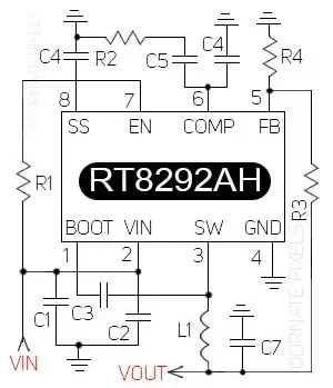
The RT8292AH is a programmable DC-to-DC IC capable of accepting a wide range of input voltages. Since various techniques control the output voltage of this IC, its devices are highly safe for that. This IC is unique for electronic devices that carry 2 ampere currents. The RT829292AH IC's output voltage is adjustable, so this ICs output volts can be changed by increasing or decreasing the value of the resistors and inductors of its bias voltage circuit. The schematic circuit diagram of RT8292AH IC and its output voltage adjustment formula are presented in this article.
The RT8292ICAH IC's input voltage range is from a minimum of 4.5 volts to a maximum of 23 volts, and the adjustable output voltage is from 0.8 volts to 20 volts. If, for any reason, the input voltage of the RT8292AH IC is lower than the specified limit and the output voltage is high, then it will shut down. This IC works as a buck converter whose operating frequency is 340 kHz.
Related IC RT8295AH Schematic Circuit Diagram
Schematic Circuit Diagram Of RT8292AH IC
The figure below is the schematic circuit diagram of the RT8292AH IC. VIN or supply voltage is input at pin1 of the IC, and the voltage is output from pin3 through L1. This circuit's output voltage depends on R2, R3, R4, and L1 values. The values of these three resistors and the inductor are determined according to the voltage divider formula to coordinate with the required operating voltage of various applications.
 |
| RT8292AH IC Schematic Circuit Diagram and Pinout |
The above circuit diagram shows the pinout or pin configuration of the RT8292AH IC.
Adjusting RT8292AH Output Voltage by Changing Component Values
- You can use the following component values to get different output voltages from the R8292AH IC.
- For 1-volt output: R2 will be 3.6KΩ, R3- 3KΩ, R4 is 12KΩ, and L1 is 2µH
- For 1.2 volts output: R2- 4.3KΩ, R3- 12KΩ, R4- 24KΩ, L1- 3.6µH
- For 1.5 volts output: R2-5.6KΩ, R3- 10.5KΩ, R4- 12KΩ, L1- 3.6µH
- For 2.5 volts output: R2- 9.1KΩ, R3- 25.5KΩ, R4- 12KΩ, L1- 6.8µH
- For 3.3 volts output: R2- 13KΩ, R3- 75KΩ, R4- 24KΩ, L1- 10µH
- For 5 volts output: R2- 20KΩ, R3- 62KΩ, R4- 11.8KΩ, L1 15µH
- For 8 volts output: R2- 33KΩ, R3- 27KΩ, R4- 3KΩ, L1- 22µH
- C1, C2, C3 - 10µF. C5- 3.3µF, C7- 33µF. R2- 13KΩ
Technical Specifications for RT8292
To fully understand the functionality of the RT8292AH, we recommend consulting the official datasheet. Find all the technical specifications you need in the RT8292AH IC PDF Datasheet.
Problems and solutions of the RT8292AH IC circuit in the Sony Bravia LED TV
If the voltage output of this regulator IC circuit is not correct, the red light of the Sony Bravia TV will blink five times. To learn more about this, watch the Informative Video about the RT8292 IC below.
Informative Video about RT8292 IC
Note: The RT8292A IC is similar to the RT8293AL, but they are not substitutes for each other regarding ampere capacity.


No comments:
Post a Comment