This page contains the PIC16F676 Digital Volt Meter Schematic Circuit Diagram Using Seven Segment Display With Programming Code Code And PCB Layout.
PIC16F676 is a widely used 14-pin PIC microcontroller IC for building various electronic projects. This article explains how to make a Digital Voltmeter using PIC16F676, PIC microcontroller IC, and a seven-segment display.
Digital Voltmeter using a PIC60F676 Microcontroller.
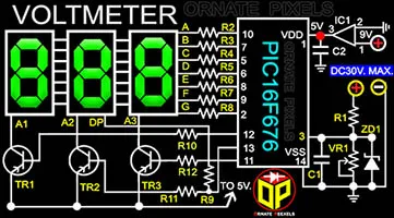
Below is a schematic circuit diagram and a high-resolution PCB layout for making a simple digital volt meter using the PIC16F676 IC. If you do not want to make a printed circuit board with a PCB layout, you can use a good-quality dot Vero board to make a Digital Volt Meter with the PIC16F676 Microcontroller.
 |
| PIC16F676 Digital Voltmeter Schematic Circuit Diagram |
This PIC16F676 digital voltmeter can measure a maximum of 30 Volts DC. For a maximum of 30-volt AC measurements, a diode and a 100 microfarad 50-volt filter capacitor can be connected to the voltage input terminal. Note that VR1 of the circuit board must be adjusted to display accurate voltage. A 9-volt DC supply is required to operate the PIC16F676 Digital Voltmeter. DC 5 volts can be applied at the points indicated in the circuit diagram.
Some technical information and support for making a Digital Voltmeter by PIC16F676 IC
A KIA7805 voltage regulator IC is used in this circuit to supply power to the PIC16F676 PIC microcontroller. Pin 1 of the KA7805 IC is for 9V input, Pin 2 for ground, and 5 volts will be output from pin 3 for operating the circuit. Some field effect transistors are used inside the PIC16F676 IC to keep the power consumption low while providing the output voltage to the seven-segment LEDs, And the drain terminals of those FETs are connected internally to pin 1 of the PIC16F676 microcontroller. That's why PIN 1 of the microcontroller is named VDD or Voltage Drain Drain, and 5 Volts supply is provided at this VDD terminal in the circuit.
Similarly, the source terminals of the FETs are connected internally to pin 14. That's why pin 14 is named VSS or Voltage Source Source. For voltage measurement, R1 inputs voltage to pin 3 of the PIC16F676 IC, and a 5-volt zener diode is connected to pin3 to ground so that no more than five volts of voltage is input to pin3.
Pins 12, 13, and 11 output the sequential switching voltage for three bases of seven-segment LED driver transistors. This PIC16F676 digital voltmeter circuit uses three BC557 transistors to flash three common anode seven-segment LEDs. A1, A2, and A3 are the anode terminals of the seven-segment LEDs, and DP is the dot point terminal.
Components List and Value Details of PIC16F676 Digital Voltmeter Circuit -
VR1= 10KΩ. R1= 47KΩ. R2, R3 R4, R5, R6, R7, R8, R13 = 100Ω. R10, R11, R12 = 1KΩ
TR1, TR2, TR3 = BC557. C1, C2 = 0.1 microfarad (104). IC1= KIA7805. Microcontroller = PIC16F676. ZD= 5V. Display - Common Anode 7 Segment LED Display x 3.
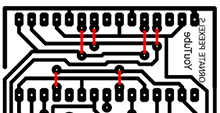
Above is a picture of the PIC60F676 digital voltmeter circuit board to help you understand where to place the components. The layout below shows where to connect the six jumpers on the bottom of the seven-segment LED display. Six jumpers should be installed in place of the red lines.
 |
| PIC60F676 Digital Voltmeter PCB Layout |
Download a high-resolution PCB layout and Open Source code from HERE to Make A PIC16F676 Digital Voltmeter.
More Post: I hope you have learned the PIC microcontroller programming method from this page. There are also more posts on Ornate Pixels on programming the ATmega8 AVR microcontroller using Arduino IDE for 4 LED Blinking.
For technical support on making the PIC16F676 digital voltmeter, please watch the video below-


No comments:
Post a Comment